- Material
- 2A12-T4
- Component
- Diode mounting bracket
- Assembly role
- Positioning and support
- Key interfaces
- Chassis and heat sink
Component and material
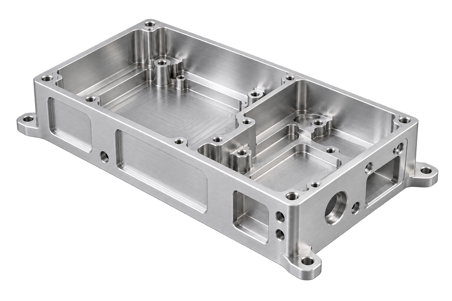
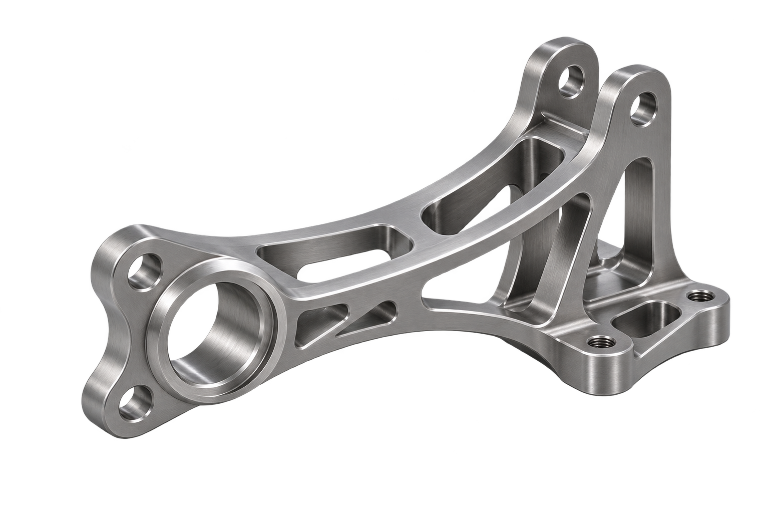
This mounting bracket uses 2A12-T4 aluminum alloy.
The bracket forms the mechanical interface between a power diode and the surrounding equipment assembly. Its requirements therefore start with the installed component, mounting surfaces and nearby connections, rather than with the bracket outline alone.
Application
It supports and positions power diodes on equipment chassis or heat sinks.
The application brief also covers fixing to a panel, keeping installation positions consistent, and supporting the component and its leads. These functions make the relationship between fixing points, lead clearances and the mounting plane central to the drawing review.
Mounting and positioning
Fixing locations need to be reviewed against the diode body and the mating assembly. The bracket should support a consistent installation position while allowing the fasteners and connections to be assembled without unwanted interference or strain on the leads.
Thermal and insulation interfaces
The metal bracket can form part of the thermal path between the diode and a heat sink. The drawing review should therefore identify the intended contact surfaces and how the bracket fits into the wider thermal assembly.
Electrical isolation is an assembly consideration. Where insulating pads or isolation features are used, their position, clearance and relationship to the metal bracket need to be defined together with the diode and heat-sink interfaces.
Features to define on the drawing
| Feature | Review focus |
|---|---|
| Fixing points | Hole locations, fastener interfaces and access for assembly |
| Mounting plane | Reference surfaces and the installed position of the diode |
| Lead clearance | Polarity, spacing and support around the electrical connections |
| Thermal contact | Defined contact surfaces between bracket, diode and heat sink |
| Insulating interfaces | Space and positioning for insulating pads or isolation features |
Assembly considerations
Mounting locations and interfaces are reviewed against assembly requirements. Electrical insulation depends on the assembly design.
The inspection plan for a bracket of this type should connect the mounting features to the drawing references. Hole positions, interface dimensions and edge condition can then be reviewed in relation to fit and assembly, with the reporting requirements stated in the order.
Planning a similar bracket
A useful RFQ includes the 2A12-T4 material callout, a dimensioned part drawing, quantity and target delivery. An assembly view showing the diode, fasteners, heat sink and any insulating parts helps explain the functional interfaces before the machining and inspection requirements are agreed.
Apply this to your own project.
Share the drawing, quantity and specification you want to review.